

KVVP Cable
What is KVVP Cable?
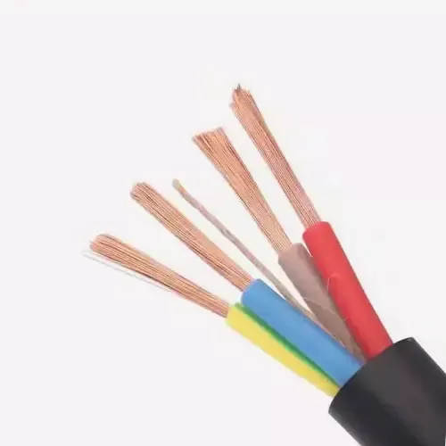
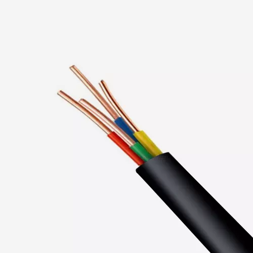
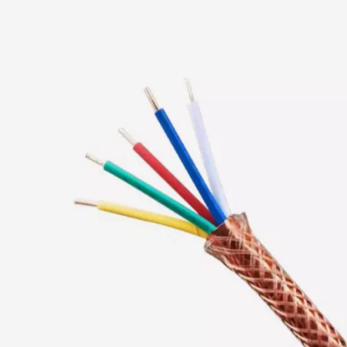
KVVP cable is a specific type of instrumentation and control cable designed for reliable signal transmission in environments susceptible to electromagnetic interference (EMI). The "K" denotes control, "V" stands for PVC insulation, the second "V" indicates PVC sheathing, and "P" signifies the presence of a braided copper shield. This shielding is the cable's defining feature, protecting the internal conductors from external electrical noise and preventing signal leakage, ensuring data integrity and accuracy in sensitive applications.
Primarily used in industrial automation, process control systems, power stations, and computerized monitoring networks, KVVP cables connect sensors, transmitters, actuators, and control panels. They are the backbone of signal transmission where precision is non-negotiable.
Key Features & Advantages of KVVP Cable
- Excellent Shielding Performance: The braided copper shield offers high coverage (typically >80%), effectively suppressing EMI and radio frequency interference (RFI).
- Stability & Accuracy: Ensures stable transmission of analog and digital signals over long distances, minimizing errors in measurement and control loops.
- Flexibility & Durability: Despite the shielding, KVVP cables maintain good flexibility for easier installation in conduits, trays, and cable ducts. The PVC outer sheath provides resistance to abrasion, oils, and mild chemicals.
- Fire Retardancy: Standard PVC compounds offer flame-retardant properties, enhancing safety in industrial settings.
- Cost-Effectiveness: Provides a robust shielding solution at a more economical point compared to some armored or specialized cables, making it a practical choice for many projects.
Technical Specifications & Parameters
Our KVVP cables are manufactured to exacting international standards (such as GB/T 9330, IEC 60502), ensuring consistent quality and performance. Below are the detailed specifications.
Construction Details
| Component | Material | Description |
|---|---|---|
| Conductor | Annealed Bare Copper | Class 2 stranded for flexibility. Available in various gauges. |
| Insulation | PVC (Polyvinyl Chloride) | Color-coded for core identification. Provides electrical isolation. |
| Shield | Braid Shield (Tinned Copper) | Braided coverage ≥ 80%. Effective high and low-frequency noise rejection. |
| Jacket / Sheath | PVC (Polyvinyl Chloride) | Robust outer protection. Available in standard black, gray, or other colors. |
Electrical & Physical Parameters
| Parameter | Typical Value / Range | Conditions / Notes |
|---|---|---|
| Nominal Voltage | 300/500V | Rated voltage U0/U. |
| Test Voltage | 2000V AC | Applied for 5 minutes during testing. |
| Insulation Resistance | ≥ 20 MΩ·km | At 20°C. |
| Temperature Range | -15°C to +70°C | Fixed installation. Short-term max up to +105°C. |
| Bending Radius | ≥ 6 x Cable Diameter | For fixed installation. |
| Shielding Effectiveness | > 60 dB | At 30 MHz, depending on braid density. |
Standard Core Configurations & Ordering Reference
| Number of Cores | Nominal Cross-Sectional Area (mm²) | Approx. Outer Diameter (mm) | Common Application |
|---|---|---|---|
| 2, 4, 6, 8, 10, 12, 14, 16, 18, 19, 24 | 0.75, 1.0, 1.5, 2.5 | Varies from ~6mm to ~20mm | Multi-channel signal transmission, control wiring. |
| 1 pair, 2 pair, 3 pair, 4 pair, 5 pair | 0.75, 1.0, 1.5 | Varies from ~6mm to ~15mm | Twisted pair configurations for differential signals, communication. |
Typical Applications of KVVP Cable
- Connection between DCS/PLC systems and field instrumentation (temperature, pressure, flow sensors).
- Wiring for motor control centers (MCCs), switchgear, and relay circuits.
- Signal transmission in power generation and distribution facilities.
- Building automation systems (BAS) for HVAC, lighting, and security controls.
- Computer room monitoring and data acquisition (SCADA) systems.
- Analog and low-frequency digital communication networks within industrial plants.
Related Products
Hot Products
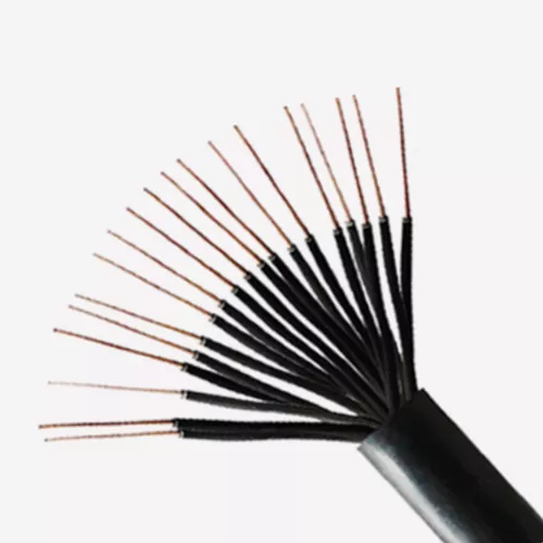
Copper Conductor PVC Insulated Sheathed Shielded Flexible Cable
If you're looking for a cost-effective, jam-resistant signal cable, then Yilan Cable, China's leading cable manufacturer, offers this high-quality Copper Conductor PVC Insulated Sheathed Shielded Flexible Cable (RVVP Cable). It is designed to combat complex electromagnetic environment, set outstanding shielding performance, high flexibility and durability in one, is to ensure that communications, automation and instrument signal purity and stability of the support.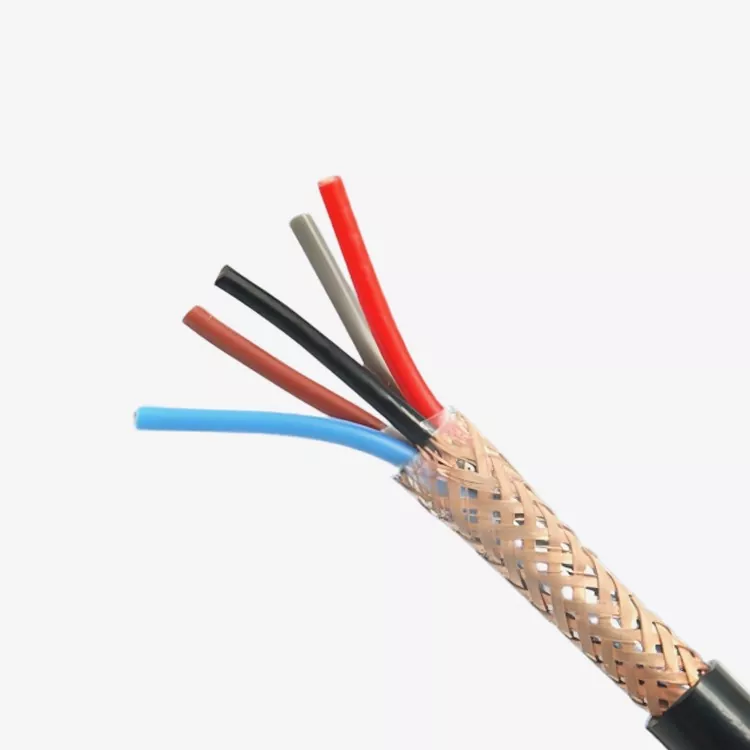
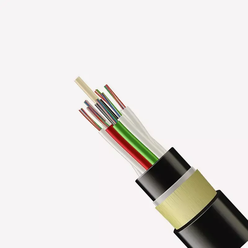
Low Smoke Halogen Free Flexible Cable
If you are looking for high quality cables with top fire protection performance and environmental protection characteristics in China market, Yilan Cable, as a professional manufacturer in China, produces high quality WD-YTTWY Low Smoke Halogen Free Flexible Cable, which realizes breakthrough upgrade on the basis of traditional rigid mineral cables. It not only can withstand high temperature above 1000°C and maintain continuous power supply, but also ensures that the project meets the highest safety standards with good flexibility and ring protection sleeve design. It also meets the forward-looking requirements of modern green buildings.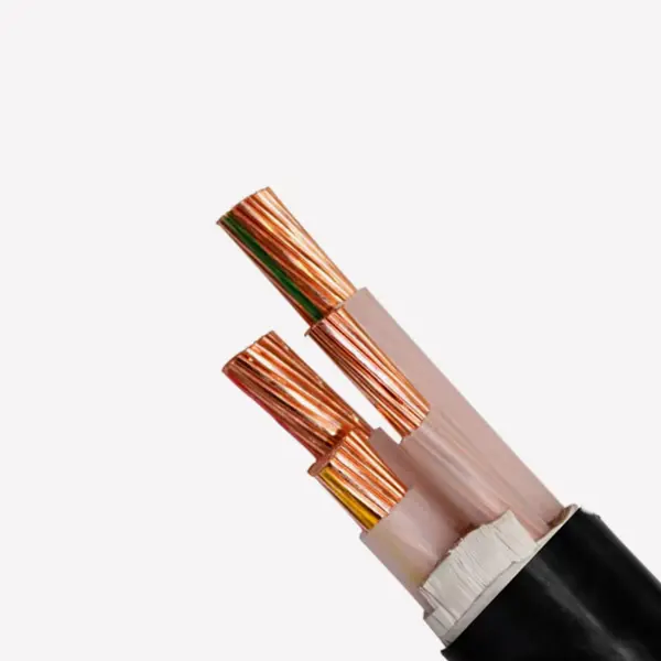
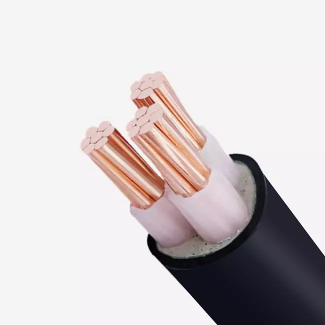
LSZH FR XLPE PVC Power Cable
Qingdao Yilan Cable Co., Ltd. high quality LSZH FR XLPE PVC Power Cable, also known as WDZ-YJV cable, is a kind of on the basis of traditional flame retardant, revolutionary realization of halogen-free, low smoke density of high quality environment-friendly flame retardant cable. It can not only actively inhibit the spread of flame in the fire, but also protect the life safety of personnel to the maximum extent. It is the core line of defense to ensure public safety in modern building electrical system.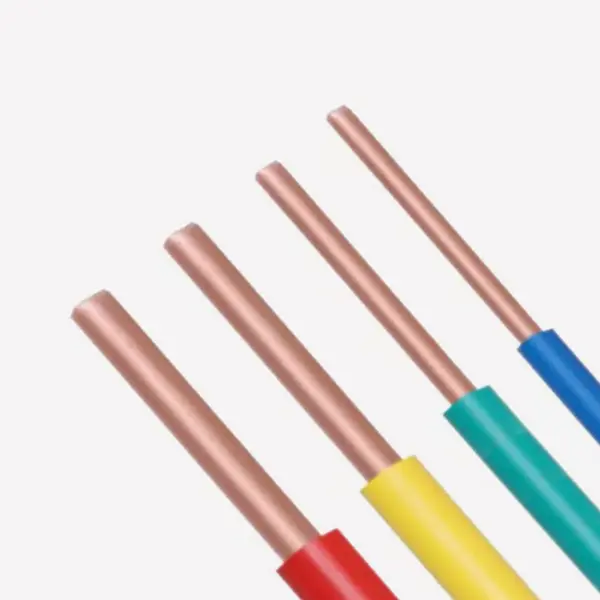
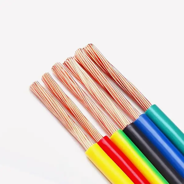
Copper PVC Insulated Cable
As a professional cable manufacturer in China, Yilan Cable would like to provide you high quality Copper PVC Insulated Cable, which uses high purity copper conductors and high quality PVC insulation to provide outstanding conductivity, insulation and mechanical strength, providing safe, durable and cost-effective support for all types of fixed installation projects.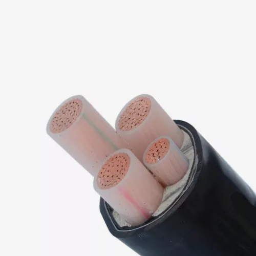
Fire Resistant PVC Insulated Sheathed STA Power Cable
If you are looking for a cost-effective cable for critical lifeline equipment such as fire pumps, emergency lighting, etc. that can continue to supply power for more than 90 minutes in a fire, then Yilan Cable, as a professional cable manufacturer in China, is the perfect choice for Fire Resistant PVC Insulated Sheathed STA Power Cable (NHVV22 Cable). It combines fire resistance, armor protection and cost advantages, especially suitable for fixed installation scenarios such as industrial direct burial, and is a support for building a strong emergency power transmission lifeline.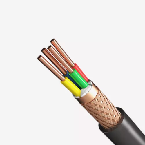
Copper Shielded PVC Insulated Sheathed Control Cable
Choose a true anti-interference product for your PLC, sensors and precision instruments. High quality Copper Shielded PVC Insulated Sheathed Control Cable manufactured by Yilan Cable factory is specially designed for complex electromagnetic environment. It not only provides excellent shielding efficiency, but also ensures durability under long-term harsh working conditions with excellent flexibility and oil resistance and wear resistance sheath.
- Related Blog
- Reviews
